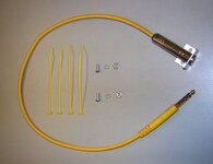
I read the modification submitted by Mega in August of "05 and thought I'd give it a try. I looked at the pictures that Mega had provided and figured it wouldn't be too tough. I used the wire and angle plug that came on the original headphones with my Ace 250. I initially cut the wires at the point where they begin to "Y" to the earphones. I drilled a 1/4 inch hole on the bottom side of the tube just ahead (on the upper side) of the hand grip. I then removed the yellow arm yoke and pryed off the plastic cap on the end of the arm tube. A 1/4 inch hole has to be drilled IN THE CENTER of the plastic plug to accomodate the 3.5MM sterio phone jack. (Jack #504K, chassis mount, 3-conductor,Philmore brand, by LKG Industries-Rockford ILL.) I placed a small rubber grommet on the wires and pulled it back to the plug so I could wiggle it into the hole in the tube to protect the wire from abraision or cutting. I then "snaked" the wires through the tube and out the back where the plug was. I removed the units' batteries and plugged the 3.5mm angle plug into the 1/4 inch adapter supplied with the 250, making sure the was enough slack to easily remove and install the smaller plug. With the wires properly positioned, I cut the wires on the opposite end so that about 2 inches were hanging out of the end of the tube. NOW THE TRICKY PART! (At least for me) I separated the 2 wires back about 1 inch. Then I stripped off 1/2 inch of insulation from both wires. Inside each of these were a bunch of very small conductors. Most of these were bare copper conductors, but there was one conductor on each side that was covered with a colored varnish or something that acted as an insulation. One side had a blue varnish and the other side had a red varnish. These are VERY SMALL wires and have to be scraped very carefully to remove the varnish so a good solder joint can be made. All the bare copper conductors can be twisted together and be soldered to the "common" terminal on the back of the phone jack. The scraped conductors must be soldered to the other 2 terminals. (one wire to each) I dobbed RTV silicone at the back of the jack to help strengthen the connection point against jarring or vibration. You can't get the job done with a big ole soldering gun, it calls for small solder and a small soldering tip. It really made a difference having the earphone wires coming from the side or the back of me. I mounted the phone jack into the plastic plug before I soldered the connections. Let the silicone set before reinserting plastic plug. Be careful when reinstalling the yellow arm yoke to not pinch the wires when pushing the guide pin through the tube. Mine works great! Sorry about being so long winded, but I wrote EVERYTHING I could think of to be as clear as possible.
Ace 250 headphone jack modification
- Thread starter Wabash
- Start date


Top Member Reactions
-
 2306
2306 -
 1113
1113 -
 1036
1036 -
 899
899 -
 838
838 -
 770
770 -
 754
754 -
 736
736 -
 606
606 -
 508
508 -
 490
490 -
 477
477 -
 447
447 -
 420
420 -
 400
400 -
 398
398 -
O
398
-
 394
394 -
 384
384 -
 376
376