Erndog
Jr. Member
- Joined
- Feb 25, 2018
- Messages
- 31
- Reaction score
- 24
- Golden Thread
- 0
- Primary Interest:
- All Treasure Hunting
- #1
Thread Owner
I have a Bounty Hunter Quick Draw II that I have had for decades. I haven't used it in quite a few years and had it sitting in my shed. I recently started getting the bug again so I dug it out of the abyss.
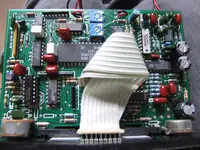
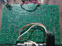
Obviously, it would not power up. Not that I would ever expect it to. However, like a real dumb ass I left the batteries in it all these years. The corrosion was bad enough to cause the tops of the batteries to tear off when I removed them. So I went out and got two new 9v connectors and just finished soldering them in a few hours ago. After painstakingly fishing everything back through the holes I reassembled the unit and mounted it. Upon turning it on I got no readout indications, beeps, or battery light. I went ahead and tried passing it over a steel splitting wedge just to ensure it wasn't working. Nope. I tore it down again and verified the battery wires were still intact and making continuity. Also verified 18v at the on/off switch. One oddity (to me); on one of the sets of battery leads, not only did I get good continuity, but when I tested from one connector terminal (+ I think) I got continuity to both the + and - on the board. However, the other wire didn't do that. I am not huge on electronics, but I suspect maybe a diode is involved. Also, the other battery connector's wires don't do this at all.
IDEAS??


