The nature of my improvement consists in a device for securing window-sash at any desired p oint of elevation and ixing the same firmly at that point, so that any pressure from without, either up or down, only tends the more firmly to fasten the sash at that point, which I accomplish by two cylindrical rollers of suitable length and diameter, so working between the windowstrip and a flange on the bedplate of the fastener (which ange being the segment of a circle and of a depth equal to the length of the rollers) that the tangent lines described by the flange and the window strip will form a wedgeshaped opening bothabove and below the center of the flange, and as the sash is raised the cylinder above rolls down into the wedgeshaped opening and impinges both on the ilange and windowstrip, thereby crowding the opposite edge of the sash against the jam or window-frame so firmly as to resist further elevation of the sash. In likernanner the lower cylinder, when acted upon by the descending sash, rolls up into the lower wedge shaped space from below and prevents the sash from descending, and it will neither move up nor down until one or both of the cylinders roll out and loosen the sash, which loosening I effect by two levers, on which are pivoted the cylinders, said levers being also pivotedv together at or near the center of the circle of which the flange is a segment, and by compressing the outward ends of the levers together the cylinders loosen and the sash is moved to any other desired point, when the levers, pushed apart by a spring, again bring the cylindrical rollers as near the apex of the wedge-shaped openings as may be, and the additional action of the ascending or descend- To enable those skilled in the art to fully understand and construct my invention, I will proceed to describe it.
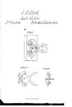
In Fig. 1, A isthe bed-plate of the fastener. B is a flange forming the segment of a circle described from a center at F. C C are cylindrical rollers, which roll on the periphery of the flange B. These rollers are pivoted to the levers D D, and are recessed so as to flush even with the under side of the said levers, and they also mesh into sections of the ange B, as seen at b b, which serves to keep them in the saine relative position to the levers D D. Said levers are pivoted at a common center, F, and operate the rollers C C. E is a -coiled wire spring which actuates the levers D D, and moves the rollers C C to their bea-ring between the flange B and window-strip L. F F F are rivets which pivot the plate A, rollers C C, and levers D D together. G is a screw which secures the fastener to the sash K. The dotted lines represent the rollers thrown out from the window-strip L by compressing the levers at d d.
In Fig. 2, A shows the reverse side of the bed-plate; C O, the rollers, and D D the levers, which are recessed into the rollers at H H. I I are projections on the plate which enter holes made in the sash, and these, with the screw at J, strongly hold the fastener to t-.., sash. "j"
Fig. 3 shows the depth of the flange B, the depth and diameter of the cylindrical rollers C C, and a section of the levers D D. The screw is shown at G, the projections at I I, and a section of the serrated flange B at b b.
The fastener is operated by compressing the outward ends of the levers 0l d, as shown by the dotted'lines in Figrl. This causes the rollers C O to leave their bearing between the flange B and window-strip L, and to roll out on the said flange, which permits the sash to be raised or lowered, as desired. By releasing the hold upon the levers the rollers are again thrown in position by the spring E acting upon the levers D D, and the sash is firmly fastened at the desired point.
What I claim as new, and desire to secure by Letters Patent, is-
The circular flange B, or its equivalent, and the peculiar-shaped rollers C C, the same being combined and operated substantially and for the purpose as set forth.


 Thanks for looking