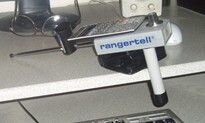
RangerTell Calculator - A Comprehensive Report..2

OP
OP
aarthrj3811

aarthrj3811

Gold Member
Apr 1, 2004
9,256
1,169
Northern Nevada
Detector(s) used
Dowsing Rods and a Ranger Tell Examiner
OP
OP
aarthrj3811

aarthrj3811

Gold Member
Apr 1, 2004
9,256
1,169
Northern Nevada
Detector(s) used
Dowsing Rods and a Ranger Tell Examiner
~SWR~
or inquiring minds, and those keeping score at home:
"Electricity" will not pass though a piece of PVC pipe.
Again....for those slightly hard of hearing or sitting in the back...."electricity" from a human will not pass though a piece of PVC pipe.
Anyone who says differently, is only soliciting the fraudulent claims made by the manufacture.

So J Player was soliciting fraudulent devices when he made this report?
Did the electricity that J Player measured not go though the plastic of the calculator?
 

OP
OP
aarthrj3811

aarthrj3811

Gold Member
Apr 1, 2004
9,256
1,169
Northern Nevada
Detector(s) used
Dowsing Rods and a Ranger Tell Examiner
J Player report
Over a several day period we made electronic tests of the calculator on the Examiner to see what signals we can detect in the air around it using a Tektronix 433 oscilloscope with a range to 35 MHz. In order to obtain the same signal the Examiner receives, we wound a coil identical to the Examiner spiral coil and positioned it below the calculator at the same location where the Examiner coil is located. The Oscilloscope probe was connected to the test coil to collect whatever signal can be detected at the back side of the calculator. We aslo ran tests without using the coil to see if any signal can be picked up in the air using only the oscilloscope probe.
The results of the calculator testing showed the Examiner calculator sends detectable signals into the air behind it that can be measured up to 5mv on an oscilloscope when using an identical pickup coil as is used inside the Examiner. This signal is strongest when the coil is held against the calculator enclosure, and diminishes as the coil is moved away from the calculator until it is not detectable at about 4-5 cm distance.
 

OP
OP
aarthrj3811

aarthrj3811

Gold Member
Apr 1, 2004
9,256
1,169
Northern Nevada
Detector(s) used
Dowsing Rods and a Ranger Tell Examiner
http://en.wikipedia.org/wiki/Electronics
Electronics is the branch of science and technology that deals with electrical circuits involving active electrical components such as vacuum tubes, transistors, diodes and integrated circuits. The nonlinear behaviour of these components and their ability to control electron flows makes amplification of weak signals possible,
~SWR:::
everyone sits around snickering as LRL proponents confuse signals for "electricity", as they are not savvy enough to know the difference:::
You got it part right
 

OP
OP
aarthrj3811

aarthrj3811

Gold Member
Apr 1, 2004
9,256
1,169
Northern Nevada
Detector(s) used
Dowsing Rods and a Ranger Tell Examiner
~SWR~
:::everyone laughs even more hysterically @ the LRL proponents as they try to do damage control:::
Yes..it is not the LRL owner/operators who need to do damage control…Are we still having fun?
 

OP
OP
aarthrj3811

aarthrj3811

Gold Member
Apr 1, 2004
9,256
1,169
Northern Nevada
Detector(s) used
Dowsing Rods and a Ranger Tell Examiner
This comprehensive report shows exactly what is behind the “main drive” of the RangerTell Examiner. Under the hood, if you will…..of a calculator. This report is being posted on TreasureNet at the request of LRL Proponents to prove that a common calculator will not transmit various frequencies by keystrokes. The merits of this report can be debated in another thread, as the creator is not present to defend this copyright protected material.

This copyright protected report is being used with the permission of its creator. More information can be found here

Without any further ado….Under the hood of the RangerTell calculator

The Rangertell Examiner Project - Report 4

Dec 14, 2009 - Calculator testing indoors


The calculator that came with the Examiner has no brand name or other marks to identify it other than "scientific calculator" printed on the front. After a member of the Geotech forum identified the calculator as looking the same as his Casio, I got to wondering if my Casio calculator was the same too. My Casio fx-300ES calculator has nearly the same buttons as the Examiner calculator, but mine has a solar power panel, while the Examiner calculator does not. I opened the backs of both calculators where the batteries are changed, and I could see they are not the same. The circuit boards are different, and the Casio has a few more components, probably associated with the power panel. The Casio has a single battery for a 1.5v supply, while the Examiner calculator uses two cells to run at 3v. The casio also had more conductors leading to the display to drive 15 digits, while the other has only 12 digits. I could see both calculators had a large drop of black epoxy covering the processor area just below the display.

The drop of epoxy is what gave me my next idea. If there is any signal coming from the calculator, then it would originate in the processor area under the epoxy. And if this signal is inductively coupled to the Examiner, I should be able to pick it up by using a coil. So I put both calculators back together and made up a 5cm diameter coil 50 turns from #18 wire and connected one end to ground, and the other end to the oscilloscope probe. First I looked at what wave form I could see in the air. I found the AC power noise at 60Hz that is usually in the lab, and I found some high frequency noise from the computers. This HF noise measured 5mv across this coil, but could be made higher if you rest your hand on top the coil. Then I put the Rangertell calculator on top the coil and saw a periodic AC spike that looked like an exponential curve about every 15us. This is the same kind of wave form I see when there is ringing after a digital signal switches. I could see a periodic fluctuation in the voltage about twice a second, similar to a heartbeat. This was later seen as a momentary voltage decrease every time the calculator curser blinked on.

I held the same coil against the Casio calculator and found it was not producing much of a signal to pick up inductively. I found the wave form was a little different on the Casio, as well as a lot weaker. There was a large spike, followed by a train of many very weak spikes that were hardly discernible, and they were at only 1/4 the frequency of the Rangertell calculator. I imagine these differences are to keep the power consumption low for the solar power and the single battery. When I slowed down the time base I could see the large periodic pulse followed by very many smaller pulses.

I made another 5cm diameter pickup coil with 3 turns and got a good signal from the Rangertell calculator with very little HF background noise from the lab. But I could not get a strong enough signal from the Casio to sync on. I think the lower voltage of the Casio produces pulses that are weaker than the threshold of noise in the lab. With the Rangertell calculator, I could trigger a signal using either coil as long as the coil was within 3cm distance from the calculator. I should point out the high frequency ripple you see along the eponential curves was almost nonexistent in the 3-turn coil. This HF ripple was not from the calculator, but noise from the lab, as you can see in the photos taken with no power on the calculator. The large sine wave is a magnified view of the HF noise taken when the calculator first triggered a pulse. These are not definitive tests. They are only what I saw when I hooked up a quick coil for a peek at what signals I could measure from behind the calculator.


Jan 09, 2010 - Calculator testing outdoors

Tests were made on the Examiner calculator outdoors to see what signals it sends out to the Examiner circuitry. These tests showed the calculator generates pulse signals that can be detected at millivolt levels up to several cm distance from the back of the calculator. Pulses from the calculator were observed at 575 Hz contained in an envelope of stronger pulses at 30 Hz. Oscilloscope images showed changes in the wave shape during the time while a calculator key was held in the pressed down position, and a fluctuation in voltage that could be identified as a slower switching rise time when the cursor was blinking on. It is presumed the pulses observed were caused by RFI noise created during the rising and falling edges of the calculator's internal frequency dividers that are timed by a an electronic clock or timer.
Outdoor test details:

Over a several day period we made electronic tests of the calculator on the Examiner to see what signals we can detect in the air around it using a Tektronix 433 oscilloscope with a range to 35 MHz. In order to obtain the same signal the Examiner receives, we wound a coil identical to the Examiner spiral coil and positioned it below the calculator at the same location where the Examiner coil is located. The Oscilloscope probe was connected to the test coil to collect whatever signal can be detected at the back side of the calculator. We aslo ran tests without using the coil to see if any signal can be picked up in the air using only the oscilloscope probe.

The calculator tests were made outdoors in order to move the calculator away from RFI noise from test equipment, computers and AC power wiring. The oscilloscope was connected to an extension cord and placed several feet away from the side of the building. The ambient noise in the air was reduced at this location, and made the small calculator signals easier to trigger and to discern than when it was tested indoors. There still remained some residual noise in the outdoor location, which was noted when making photos of the calculator signals.

The results of the calculator testing showed the Examiner calculator sends detectable signals into the air behind it that can be measured up to 5mv on an oscilloscope when using an identical pickup coil as is used inside the Examiner. This signal is strongest when the coil is held against the calculator enclosure, and diminishes as the coil is moved away from the calculator until it is not detectable at about 4-5 cm distance.


We also observed other locations on the calculator that generate stronger signals than the signal seen where the Examiner coil is located. These signals varied in shape and strength, depending on where the coil is held against the calculator. The strongest signals were detected at the display and the large navigation button just below the display on the front side of the calculator (this is the area where the processor is located under the black epoxy drop). Signals from the back side of the calculator also showed the strongest signals at the same locations at the front, but they were about 3/4 the strength of the signals seen on the front side. The Examiner coil is centered 4cm below the strongest signals on the back of the calculator at a location where the power supply wires are soldered to the keypad conductors. The signal at this location was seen to be about half the strength of the stronger signals found near the processor and display, and it was inverted, showing opposite polarity spikes as the signal seen at the display area.


Oscilloscope images

Most of the tests were done with the oscilloscope set to the 2mV scale at various time sweeps. The screen showed pulse trains coming from the calculator that could be detected using the coil, or by using a plain alligator clip held against the calculator to show the same signals with only slight differences seen on the screen. The fastest calculator pulses we measured were 575Hz periodic spikes, contained within a 30Hz envelope that began with a large spike. The signals emanating from the calculator were determined by first looking at the ambient noise signal with the calculator removed, then moving the coil from the open air to the back of the calculator to see what new signals the calculator added to the ambient noise. The first signs of a signal were seen at 4-5cm distance from the back surface of the calculator enclosure. This was also done with the calculator turned off to check whether the calculator added any noise when it was not running (it did not add noise when it was turned off).


The images above showing the smaller time frames are actually taken from the plain alligator clip as a sensor, which showed a similar timing image as when using the coil. After taking readings for several hours, it became apparent that different components of the wave shape of these pulses could be accentuated by moving the probe or coil to different locations on the calculator surface, and by adjusting the oscilloscope probe and ground for different connection methods, as well as different triggering adjustments. But regardless of the method of measuring, the signals seen at the back of the calculator location where the Examiner spiral coil sees it remained the same except for a momentary change in the signal while a calculator button is held down, and a change in the rising edge of the first pulse caught by the trigger when the calculator curser blinked on. The signal returned to an identical signal when the button is released and the cursor blinked off.

Measuring the signals inside the calculator

After some hours of looking at the signals that can be picked up outside the calculator, I decided to measure the actual signals inside to see what is really there. This was done by connecting the probe ground to the negative terminal of the calculator battery and checking the signal at various conductors on the circuit board. I paid special attention to the conductors in the area where the Examiner coil is positioned.


© 2009 - J_P All rights reserved. Contact [email protected] for permission.


--------------------------------------------------------------------------------

The true value of the gold may be the story itself, a testament to man’s ability to believe anything for a chance at such a vast fortune.


Tags: RANGERTELL calculator Comprehensive Report
Pages: [1] Go Up
 

fenixdigger

Hero Member
Feb 8, 2010
839
44
Detector(s) used
Aurora Aqua, Excalibur, Garrett CX2, Gemini-3, MFD's, Sovereign, Viper, E Trac, Dees Nutz rod, Tesoro Sand Shark. Pro pulse.
Chortles*** The EE that thinks he reads the difference, from someone that DOES the difference
 

OP
OP
aarthrj3811

aarthrj3811

Gold Member
Apr 1, 2004
9,256
1,169
Northern Nevada
Detector(s) used
Dowsing Rods and a Ranger Tell Examiner
Lets see..Yesterday we proved that Calculator would deliver a signal through the plastic to the coil below. Next we started to talk about how the power was delivered to the electronics in the box. Then the discussion went south.

If anyone wants to know how much voltage runs between their hands all you need is a volt meter that will read MV voltage..I have between 90 and 120 MV’s running between my hands. Why this voltage varies I do not know.
The voltage enters the Ranger Tell box through the handle. It goes to a ohm potentiometer which on my model controls the sensitivity and the weight check feature. It just acts like a voltage regulator. I don’t know the values of the other coils and dadas so I can not procede…Art
 

OP
OP
aarthrj3811

aarthrj3811

Gold Member
Apr 1, 2004
9,256
1,169
Northern Nevada
Detector(s) used
Dowsing Rods and a Ranger Tell Examiner
~SWR~
For anyone who wants to know how voltage from ones hand goes though foam-rubber wrapped around PVC pipe...it will not. This is a complete, and total fabrication by someone who knows squat about electricity/electronics.
If anyone wants to find out for themselves, all you need is a volt meter that will read MV voltage. Hold one probe firmly in one hand, attach the other probe to a short piece of PVC pipe. Then grasp the PVC pipe (no cheating, don't grasp where the probe is attached) with the other hand. Notice the needle on your meter has not moved.
There now. You've just proved that voltage will not leave your hand and travel through PVC pipe. Also noticeable, is the foam-rubber is not needed for this experiment to debunk the pro-fraudsters
Gee SWR..I will include a photo of my Ranger Tell..I do not use foam rubber on my handle..I also keep my little finger on the end of the rod that comes out the bottom of the handle..I find that it works must better for me if I do this…

Could you please put the analyzes of the plastic handle that proves it is PVC pipe? .So could you tell us what happens inside the Ranger Tell unit when you add @100 mv from the human hand to the rest of the circuits when used in this manner?...Art
 

Attachments

  • ex_002.jpg
    ex_002.jpg
    12.4 KB · Views: 556
OP
OP
aarthrj3811

aarthrj3811

Gold Member
Apr 1, 2004
9,256
1,169
Northern Nevada
Detector(s) used
Dowsing Rods and a Ranger Tell Examiner
Could you please put the analyzes of the plastic handle that proves it is PVC pipe? .So could you tell us what happens inside the Ranger Tell unit when you add @100 mv from the human hand to the rest of the circuits when used in this manner?...Art

Sorry to ask all these easy questions SWR..Sorry to put you on the spot as I know you have never saw a real Ranger Tell or any LRL ..Art
 

OP
OP
aarthrj3811

aarthrj3811

Gold Member
Apr 1, 2004
9,256
1,169
Northern Nevada
Detector(s) used
Dowsing Rods and a Ranger Tell Examiner
~SWR~
Again... anybody who claims they can hold an item with only one hand, and the electrical impulses generated by the human body travel though/into that that item is doing so with either the intent to commit fraud, or simply electronically illiterate.
Statements that the device must be held by a human to operate usually indicate dowsing devices.
http://www.ncjrs.gov/pdffiles1/nij/178913.pdf
Darn..Where have I saw a similar statement..I remember now..It was when you claimed that a Calculator did not produce a signal..So are you now admitting that you are electronically challenged?
 

fenixdigger

Hero Member
Feb 8, 2010
839
44
Detector(s) used
Aurora Aqua, Excalibur, Garrett CX2, Gemini-3, MFD's, Sovereign, Viper, E Trac, Dees Nutz rod, Tesoro Sand Shark. Pro pulse.
Now wait Art, Sparky Sr. used the words ergo and usually. Things are looking up. Have we mentioned what pvc and static electricity

may have in common? Could "movement" and pvc equal static?? Nah,
 

OP
OP
aarthrj3811

aarthrj3811

Gold Member
Apr 1, 2004
9,256
1,169
Northern Nevada
Detector(s) used
Dowsing Rods and a Ranger Tell Examiner
~Art~
Darn..Where have I saw a similar statement..I remember now..It was when you claimed that a Calculator did not produce a signal..So are you now admitting that you are electronically challenged?
Sorry SWR about this post..I may have drank to may 802’s..My ego may be getting ahead of me. The fact that I have been right about electronics more than you have is probably just a lucky guess..After all the only thing I know is how these tools operate.
Hey LT..great post..I forgot about “static electricity”..It does have more punch than MV voltage and will discharge on almost any surface..Art
http://amasci.com/emotor/voltmeas.html
Google:


"Static Electricity" means "High Voltage"
Measuring your body-voltage
1999 William J. Beaty
"Static electricity" is not electricity which is static.
Actually, the thing we call Static electricity is an imbalance in the amounts of positive and negative charges found within the surface of an object. It's only the imbalance between opposite charges which is important. It's irrelevant whether the charge is moving or "static." In fact, the charge-imbalance can flow along as an electric current, yet it loses none of it's familiar "static electrical" properties. The charge still crackles, glows, and attracts dust and lint, even when it's moving along.) But how can we have "static" that flows? Motionless motion? Simple. "Static electricity" is all about charge-imbalance, and it has nothing to do with charges at rest. "Static electricity" was misnamed.
Then what is "static electricity?" Here's a big clue. There's always a strong e-field (electric field) surrounding these charges, whether the charges are moving still. This e-field is the main feature of so-called "static" electricity. But what's an e-field? One way to say it: an e-field is like a magnetic field, but it's electrical in nature. Another simple answer: an electric field is a voltage without a current; whenever you have pure voltage, then you have a pure electric field with no magnetism involved. Still another way to say it:
"STATIC ELECTRICITY" is not unmoving, it really means "HIGH VOLTAGE ELECTRICITY."
 

OP
OP
aarthrj3811

aarthrj3811

Gold Member
Apr 1, 2004
9,256
1,169
Northern Nevada
Detector(s) used
Dowsing Rods and a Ranger Tell Examiner
~SWR~
So far, the Electrical Engineers have furnished "proof positive" that the device built and sold by RangerTell is fraudulent, and cannot perform as advertised. The calculator mounted on top of the spinning box with an antenna sticking out of it serves no useful purpose, as the keystrokes do not create various frequencies.

It must be that reading comprehension thing again..An EE.. J Player wrote a report on the Calculator used on the device and it was posted here by another EE..
After a member of the Geotech forum identified the calculator as looking the same as his Casio
I opened the backs of both calculators where the batteries are changed, and I could see they are not the same. The circuit boards are different,
The Casio has a single battery for a 1.5v supply, while the Examiner calculator uses two cells to run at 3v.
The casio also had more conductors leading to the display to drive 15 digits, while the other has only 12 digits.
. I could see both calculators had a large drop of black epoxy covering the processor area just below the display.
With the Rangertell calculator, I could trigger a signal using either coil as long as the coil was within 3cm distance from the calculator. I should point out the high frequency ripple you see along the eponential curves was almost nonexistent in the 3-turn coil. This HF ripple was not
Tests were made on the Examiner calculator outdoors to see what signals it sends out to the Examiner circuitry. These tests showed the calculator generates pulse signals that can be detected at millivolt levels up to several cm distance from the back of the calculator.
In order to obtain the same signal the Examiner receives, we wound a coil identical to the Examiner spiral coil and positioned it below the calculator at the same location where the Examiner coil is located.
The results of the calculator testing showed the Examiner calculator sends detectable signals into the air behind it that can be measured up to 5mv on an oscilloscope when using an identical pickup coil as is used inside the Examiner.


So SWR…J.player has proved that the Examiner Calculator produces a signal…That is what my experiments have proven by using a set of rods..So could you tell us what happens inside the Ranger Tell unit when you add @100 mv from the human hand to the rest of the circuits?..Art
 

fenixdigger

Hero Member
Feb 8, 2010
839
44
Detector(s) used
Aurora Aqua, Excalibur, Garrett CX2, Gemini-3, MFD's, Sovereign, Viper, E Trac, Dees Nutz rod, Tesoro Sand Shark. Pro pulse.
Let's try this,, It's magic!!!!
 

OP
OP
aarthrj3811

aarthrj3811

Gold Member
Apr 1, 2004
9,256
1,169
Northern Nevada
Detector(s) used
Dowsing Rods and a Ranger Tell Examiner
Hey LT…I was thinking about Magic yesterday…When I was 10 years old I saw the magic of seeing people talk in a magic box..Just Sunday I drove from California to my house in 2 hours…The first time I made that trip it took 6 hours…This has all happened because someone had a thought and made it happen…Art
 

fenixdigger

Hero Member
Feb 8, 2010
839
44
Detector(s) used
Aurora Aqua, Excalibur, Garrett CX2, Gemini-3, MFD's, Sovereign, Viper, E Trac, Dees Nutz rod, Tesoro Sand Shark. Pro pulse.
Dang, those people thinking again. I had just got used to things like slide rules and 4 channels on the TV. I hope they drive off the edge of the earth on their fancy "highways" .
 

lostcauses

Bronze Member
Feb 4, 2008
1,487
34
"If anyone wants to find out for themselves, all you need is a volt meter that will read MV voltage."

Ever here of static electricity. A different kind of meter is needed for such.

Not that I believe these things work, but careful.

The reality is such that the ones that make the claims have to prove them. No one needs to disprove them.

Of course this comes to the double blind test.
 

OP
OP
aarthrj3811

aarthrj3811

Gold Member
Apr 1, 2004
9,256
1,169
Northern Nevada
Detector(s) used
Dowsing Rods and a Ranger Tell Examiner
~SWR~
Fortunately, most people with an iota of sense about electricity, knows that you need two poles to complete the circuit. In other words... just touching something with one hand, will not generate an electrical discharge. One would have to have the device/implement held between both hands.
You forgot about the feet being a natural ground.
Ergo, anybody who claims they can hold an item with only one hand, and the electrical impulses generated by the human body travel though/into that that item is doing so with either the intent to commit fraud, or simply electronically illiterate.
No fraud at all.,.just facts that everyone understands
Thanks, and a tip of the hat to JP for proving that a common calculator will not produce various frequencies that can be used for "treasure hunting", as the pro-fraudsters solicit

RangerTell Calculator - A Comprehensive Report
No need to go to that web site. It is all here on this thread where SWR can not delete our answers
http://forum.treasurenet.com/index.php/topic,393152.msg2895358.html#msg2895358
ter a member of the Geotech forum identified the calculator as looking the same as his Casio
I opened the backs of both calculators where the batteries are changed, and I could see they are not the same. The circuit boards are different,
The Casio has a single battery for a 1.5v supply, while the Examiner calculator uses two cells to run at 3v.
The casio also had more conductors leading to the display to drive 15 digits, while the other has only 12 digits.
. I could see both calculators had a large drop of black epoxy covering the processor area just below the display.
With the Rangertell calculator, I could trigger a signal using either coil as long as the coil was within 3cm distance from the calculator. I should point out the high frequency ripple you see along the eponential curves was almost nonexistent in the 3-turn coil. This HF ripple was not
Tests were made on the Examiner calculator outdoors to see what signals it sends out to the Examiner circuitry. These tests showed the calculator generates pulse signals that can be detected at millivolt levels up to several cm distance from the back of the calculator.
In order to obtain the same signal the Examiner receives, we wound a coil identical to the Examiner spiral coil and positioned it below the calculator at the same location where the Examiner coil is located.
The results of the calculator testing showed the Examiner calculator sends detectable signals into the air behind it that can be measured up to 5mv on an oscilloscope when using an identical pickup coil as is used inside the Examiner.


So SWR…J.player has proved that the Examiner Calculator produces a signal…That is what my experiments have proven by using a set of rods..So could you tell us what happens inside the Ranger Tell unit when you add @100 mv from the human hand to the rest of the circuits?..Art
http://forum.treasurenet.com/index.php/topic,393152.msg2895859.html#msg2895859
Full text of http://forum.treasurenet.com/index.php/topic,393139.0.html
This comprehensive report shows exactly what is behind the “main drive” of the RangerTell Examiner. Under the hood, if you will…..of a calculator. This report is being posted on TreasureNet at the request of LRL Proponents to prove that a common calculator will not transmit various frequencies by keystrokes. The merits of this report can be debated in another thread, as the creator is not present to defend this copyright protected material.

This copyright protected report is being used with the permission of its creator. More information can be found here

Without any further ado….Under the hood of the RangerTell calculator

The Rangertell Examiner Project - Report 4

Dec 14, 2009 - Calculator testing indoors


The calculator that came with the Examiner has no brand name or other marks to identify it other than "scientific calculator" printed on the front. After a member of the Geotech forum identified the calculator as looking the same as his Casio, I got to wondering if my Casio calculator was the same too. My Casio fx-300ES calculator has nearly the same buttons as the Examiner calculator, but mine has a solar power panel, while the Examiner calculator does not. I opened the backs of both calculators where the batteries are changed, and I could see they are not the same. The circuit boards are different, and the Casio has a few more components, probably associated with the power panel. The Casio has a single battery for a 1.5v supply, while the Examiner calculator uses two cells to run at 3v. The casio also had more conductors leading to the display to drive 15 digits, while the other has only 12 digits. I could see both calculators had a large drop of black epoxy covering the processor area just below the display.

The drop of epoxy is what gave me my next idea. If there is any signal coming from the calculator, then it would originate in the processor area under the epoxy. And if this signal is inductively coupled to the Examiner, I should be able to pick it up by using a coil. So I put both calculators back together and made up a 5cm diameter coil 50 turns from #18 wire and connected one end to ground, and the other end to the oscilloscope probe. First I looked at what wave form I could see in the air. I found the AC power noise at 60Hz that is usually in the lab, and I found some high frequency noise from the computers. This HF noise measured 5mv across this coil, but could be made higher if you rest your hand on top the coil. Then I put the Rangertell calculator on top the coil and saw a periodic AC spike that looked like an exponential curve about every 15us. This is the same kind of wave form I see when there is ringing after a digital signal switches. I could see a periodic fluctuation in the voltage about twice a second, similar to a heartbeat. This was later seen as a momentary voltage decrease every time the calculator curser blinked on.

I held the same coil against the Casio calculator and found it was not producing much of a signal to pick up inductively. I found the wave form was a little different on the Casio, as well as a lot weaker. There was a large spike, followed by a train of many very weak spikes that were hardly discernible, and they were at only 1/4 the frequency of the Rangertell calculator. I imagine these differences are to keep the power consumption low for the solar power and the single battery. When I slowed down the time base I could see the large periodic pulse followed by very many smaller pulses.

I made another 5cm diameter pickup coil with 3 turns and got a good signal from the Rangertell calculator with very little HF background noise from the lab. But I could not get a strong enough signal from the Casio to sync on. I think the lower voltage of the Casio produces pulses that are weaker than the threshold of noise in the lab. With the Rangertell calculator, I could trigger a signal using either coil as long as the coil was within 3cm distance from the calculator. I should point out the high frequency ripple you see along the eponential curves was almost nonexistent in the 3-turn coil. This HF ripple was not from the calculator, but noise from the lab, as you can see in the photos taken with no power on the calculator. The large sine wave is a magnified view of the HF noise taken when the calculator first triggered a pulse. These are not definitive tests. They are only what I saw when I hooked up a quick coil for a peek at what signals I could measure from behind the calculator.


Jan 09, 2010 - Calculator testing outdoors

Tests were made on the Examiner calculator outdoors to see what signals it sends out to the Examiner circuitry. These tests showed the calculator generates pulse signals that can be detected at millivolt levels up to several cm distance from the back of the calculator. Pulses from the calculator were observed at 575 Hz contained in an envelope of stronger pulses at 30 Hz. Oscilloscope images showed changes in the wave shape during the time while a calculator key was held in the pressed down position, and a fluctuation in voltage that could be identified as a slower switching rise time when the cursor was blinking on. It is presumed the pulses observed were caused by RFI noise created during the rising and falling edges of the calculator's internal frequency dividers that are timed by a an electronic clock or timer.
Outdoor test details:

Over a several day period we made electronic tests of the calculator on the Examiner to see what signals we can detect in the air around it using a Tektronix 433 oscilloscope with a range to 35 MHz. In order to obtain the same signal the Examiner receives, we wound a coil identical to the Examiner spiral coil and positioned it below the calculator at the same location where the Examiner coil is located. The Oscilloscope probe was connected to the test coil to collect whatever signal can be detected at the back side of the calculator. We aslo ran tests without using the coil to see if any signal can be picked up in the air using only the oscilloscope probe.

The calculator tests were made outdoors in order to move the calculator away from RFI noise from test equipment, computers and AC power wiring. The oscilloscope was connected to an extension cord and placed several feet away from the side of the building. The ambient noise in the air was reduced at this location, and made the small calculator signals easier to trigger and to discern than when it was tested indoors. There still remained some residual noise in the outdoor location, which was noted when making photos of the calculator signals.

The results of the calculator testing showed the Examiner calculator sends detectable signals into the air behind it that can be measured up to 5mv on an oscilloscope when using an identical pickup coil as is used inside the Examiner. This signal is strongest when the coil is held against the calculator enclosure, and diminishes as the coil is moved away from the calculator until it is not detectable at about 4-5 cm distance.


We also observed other locations on the calculator that generate stronger signals than the signal seen where the Examiner coil is located. These signals varied in shape and strength, depending on where the coil is held against the calculator. The strongest signals were detected at the display and the large navigation button just below the display on the front side of the calculator (this is the area where the processor is located under the black epoxy drop). Signals from the back side of the calculator also showed the strongest signals at the same locations at the front, but they were about 3/4 the strength of the signals seen on the front side. The Examiner coil is centered 4cm below the strongest signals on the back of the calculator at a location where the power supply wires are soldered to the keypad conductors. The signal at this location was seen to be about half the strength of the stronger signals found near the processor and display, and it was inverted, showing opposite polarity spikes as the signal seen at the display area.


Oscilloscope images

Most of the tests were done with the oscilloscope set to the 2mV scale at various time sweeps. The screen showed pulse trains coming from the calculator that could be detected using the coil, or by using a plain alligator clip held against the calculator to show the same signals with only slight differences seen on the screen. The fastest calculator pulses we measured were 575Hz periodic spikes, contained within a 30Hz envelope that began with a large spike. The signals emanating from the calculator were determined by first looking at the ambient noise signal with the calculator removed, then moving the coil from the open air to the back of the calculator to see what new signals the calculator added to the ambient noise. The first signs of a signal were seen at 4-5cm distance from the back surface of the calculator enclosure. This was also done with the calculator turned off to check whether the calculator added any noise when it was not running (it did not add noise when it was turned off).


The images above showing the smaller time frames are actually taken from the plain alligator clip as a sensor, which showed a similar timing image as when using the coil. After taking readings for several hours, it became apparent that different components of the wave shape of these pulses could be accentuated by moving the probe or coil to different locations on the calculator surface, and by adjusting the oscilloscope probe and ground for different connection methods, as well as different triggering adjustments. But regardless of the method of measuring, the signals seen at the back of the calculator location where the Examiner spiral coil sees it remained the same except for a momentary change in the signal while a calculator button is held down, and a change in the rising edge of the first pulse caught by the trigger when the calculator curser blinked on. The signal returned to an identical signal when the button is released and the cursor blinked off.

Measuring the signals inside the calculator

After some hours of looking at the signals that can be picked up outside the calculator, I decided to measure the actual signals inside to see what is really there. This was done by connecting the probe ground to the negative terminal of the calculator battery and checking the signal at various conductors on the circuit board. I paid special attention to the conductors in the area where the Examiner coil is positioned.


© 2009 - J_P All rights reserved. Contact [email protected] for permission.
 

Top Member Reactions

Users who are viewing this thread

Top