What's new

Need Seismic Refraction processing Software

Seden1954

Tenderfoot
Joined
Feb 23, 2022
Messages
8
Reaction score
13
Golden Thread
0
I bought a Bison 5012 Seismograph and am having trouble finding opensource software that accepts SEG-1 format or allows entering the shot data manually. If anyone has some legacy software that I could buy from you I would appreciate it. I don't care if it's DOS as I have a Windows 98 laptop to run it. Thank you in advance for your help.
 
Hi there Seden!

It has been a while! If you are still around, I can help with this. If not, this thread can continue in posterity!

There are a few very nice reds on the subject. I will provide links to those.

The concept involves Normal Move Out (NMO). NMO is measured using the travel time across the surface between geophones extended in a line over the surface. The surface wave is the first arrival at the geophones!

Knowing the distance and time, A simple Time-Speed-Distance calculation can be done to determine speed.

Time = Speed x distance. Speed = distance / time. Using a system of seconds, feet, speed comes out as feet per second.

You now know Speed aka velocity. With velocity, we can get distance to bedrock.


How? The next arrivals are from the subsurface! :hello:

Stick around! There's more! :)

- Geowizard
 
Positive feedback for EPA:

EPA provides FREE tutorials. Our tax $$$$ well spent IMHO! :)

Saves pages and pages of posts on TreasureNet too!

Here's a link:


Stick around! There's more! :)

- Geowizard
 
Here's more!

The software part... In a past life, I was an Electronics Instructor in a post-secondary technical school. :occasion14:

I would ask my class how many of YOU are programmers?

No hands raised.

I would respond with... You're all programmers! :confused:

How many of you put your clothes on and take a shower?

If you take a shower and then put your clothes on - You are a programmer! :)

Stick around! You know why?

- Geowizard
 
There's more to know:

Understanding the configuration of the geophones, an acoustic waveform is introduced at the "Shot point".

There are shot gun "shots" and hammer strikes for openers that introduce an acoustic waveform called a "P" wave. The waveform has a compression "P" component and a shear "S" component. A switch closure by a switch closes a circuit that marks the start of the "time" measurement. Then we "wait" for the arrival of the P wave at each geophone.

Its all about time - speed - distance.

Ultimately distance to bedrock can be determined.

Speed of the P wave on the surface, called "surface wave" through the ground:

Speed = Distance/Time

We know the distance from the shot to the first geophone. We need a handy-dandy stop watch that measures Time in microseconds. How do we do that? :confused:

Smart phones have a timer. The problem is that the "event" is over before you perceive the shot.

Stick around and find out how we do that!

- Geowizard
 
Nobody talks about this:

A microcontroller is a computer on a chip. It uses instructions that make a program. A program can be used to measure time in microseconds. It takes time and self-study to know how to do that programming.

We can make this happen. I have microcontrollers and I can program them! :)

I will get back to this shortly.

- Geowizard
 
How many of you put your clothes on and take a shower?

If you take a shower and then put your clothes on - You are a programmer! :)
I’ve known plenty of people who could take a shower and put their clothes on, but were most definitely not programmers.
 
You're a programmer if...

You are taking a shower and putting your clothes on. That's a logical sequence. It's a program we can call "getting dressed"! ::)

- Geowizard
 
Seismic processing software:

The options are "real time" during the survey or "post processing" after the survey.

Real Time processing requires a computer on site at the survey and connected to geophones. The computer has the survey parameters loaded in memory. The computer measures time. It knows distance from shot point to geophone(s). It calculates depth to bedrock based on time speed and distance using trigonometry.

Post Processing uses "time" data collected from a survey that is stored on a memory card. The depth(s) are calculated (processed) later.

One obvious application is in placer gold mining.

- Geowizard
 
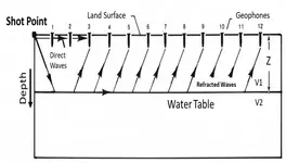
Using the schematic;

Using the reference in post #3 above, and viewing the schematic will provide the casual observer a few clues as to the process of acoustic waves traveling across and through the ground.

refraction_conceptual_diagram.webp

The travel time of the Direct wave (distance is known) across the ground between shot point and Geophone(s) is used to calculate (V1) and (V2). Based on reflection time(s), the distance(s), Depth (Z) can be calculated.

We aren't done, so stick around! There's more! :)

Geowizard
 
Last edited:
The shot point:

The shot point used in small, shallow seismic surveys is made with a sledge hammer and a strike plate. The sledge hammer shouldn't need much explanation. The strike plate is a steel plate having a dimension of about 18 inches x 18 inches and 1/4 inch thickness. Dimensions are not critical. The strike plate must be large enough to transfer the energy from a sledge hammer strike to the ground.

The hammer and plate form a contacts in a switch. When the hammer strikes the plate, contact is made between the hammer and the plate. That time is referred to as Time zero "T0".

Two wires are used. One wire is attached to the hammer and the other wire is attached to the plate. The wire ends can be stripped and tinned with solder. Then terminals can be crimped onto the wire ends. I drilled and tapped screw holes on the hammer and plate to make electrical connections to them. The wire to the plate only needs to be at the edge so as to be out of the way of the hammer strikes. The wire on the hammer should be taped or wire tied to the hammer handle for strain relief.

Next is the trigger circuit.

Stick around! There's more! :)

- Geowizard
 
The trigger circuit:

The trigger circuit can be made using a resistor and a 4.7 Volt lithium battery. The battery is connected in series with a 10K ohm resistor, the two switch wires and computer ground. the series circuit is constructed with battery negative terminal connected to one end of the resistor. The other end of the resistor is connected to the hammer wire. The switch wire from the strike plate is connected to computer ground. The node where the hammer wire is connected to the resistor is the "trigger" connection.

When the hammer strikes the strike plate, the contacts are closed. The voltage at the "node" where the resistor is connected to the switch wire will switch from 4.7 volts to computer ground (0 volts) the instant the hammer strikes the strike plate.

Time is measured from the hammer strike, Time (T0) until the Direct wave arrives at the Geophone(s). The time is measured in milliseconds (thousandths of a second)!

Next, we need a stop watch that measures in milliseconds!

Stick around. :)

Geowizard
 
Last edited:
Finding a microsecond stop watch:

The two easy methods of measuring time in microseconds are "oscilloscope" and "microprocessor".

The oscilloscope option:
An off the shelf portable oscilloscope can be used to measure time in microseconds. These are battery operated instruments with two leads called probes. Each probe has an outer shield connection and a center measuring connection. A third connector on the oscilloscope may be an "external trigger" connector. The oscilloscope usually has two measuring channels. Depending on the oscilloscope, triggering can be selected to be on one or the other input measuring channels.

Next, we will look at the other option. :)

So, stick around!

- Geowizard
 
Using a microprocessor or microcontroller to measure time:

You don't have to be gifted to make a DIY microcontroller board.

Kiddos in grade school and high school are learning how to use off-the-shelf plug and play microcontroller boards like the Arduino. Do a search for Arduino UNO or Arduino Nano on Amazon.

Arduino store link:

- Geowizard
 
The Geophone:

A geophone is a highly sensitive transducer that converts ground movement (velocity) into voltage, acting as a "microphone for the earth" to detect seismic vibrations. Used primarily in oil/gas exploration and earthquake monitoring, these devices typically use a suspended magnet and coil to measure vertical or horizontal vibrations, often in the 5-500 Hz range.


- Geowizard
 
Geophone data, specs, where to buy:

Caveat: Not a sales reference - only a reference for product info.! :)

Seis-tech:


- Geowizard
 
The software:

Software is "platform dependent". That means software depends on the computer and the operating system.

The first objective is the "Time" in milliseconds from "T0" to the "P wave" arrival at the geophone.

If using an oscilloscope, measure the time and divide by the number of feet. That gives milliseconds per foot. to get the reciprocal, Velocity, invert milliseconds per foot by dividing 1 by milliseconds per foot = feet per millisecond. An example: .01 milliseconds per foot = 1 / .01 = 100 feet per millisecond. :)

On a computer using BASIC:

One computer language is BASIC. In BASIC, The program is:

Y = 100
X = 1 / Y
PRINT X
END

- Geowizard
 
Last edited:
The calculation (caution! It's a math problem):

Speed of sound in soil:

Looser, sandy soils have lower speeds (100–600 m/s, while compacted clay or gravel is faster (400–1200 m/s).
Saturated soils have much higher speeds, sometimes reaching up to (1700 m/s) (similar to water).
Greater bulk density and increased pressure at depth generally increase the speed of sound.
Compressional waves (P-waves) travel faster, generally in the (100–1700 m/s) range, while shear waves (S-waves) are generally slower.
Dry/Loose Soil: (approx. 86–260 m/s).
Saturated Sand/Clay: (1000–1700 m/s).
Solid Rock/Well-Compacted: (> 2000 m/s).

A common approximation for general, mixed soil near the surface is roughly (150 m/s).

Time, Speed (velocity), Distance:

Measured Time: 100 milliseconds.
Distance: 10 meters. from shot point to geophone
Velocity = 10 meters / 0.1 second = 100 meters per second.

Next, calculation of depth to bedrock.

- Geowizard
 
Last edited:
Now for an executable compiled from BASIC that runs on Windows...

Stay tuned. :)

- Geowizard

 
The program is self-explanatory:

This program solves the problem of calculating depth to bedrock using the seismic system under discussion.
The seismic system provides a time measurement which forms the hypotenuse of a right triangle.
The input of distance_shot_to_geophone is divided by two to form opposite side.
The depth_to_bedrock variable is the base or adjacent side to the triangle.
With an appropriate compiler, this program can be compiled into a functional .exe that runs on Windows.

'TITLE: seismic depth.BAS
'AUTHOR: Geowizard

'REVISED: 5-03-2026
'================================
#COMPILE EXE
#DIM ALL
'=============================
FUNCTION PBMAIN () AS LONG
'=============================
'Define variables:

DIM time_shot_to_geophone AS SINGLE
DIM time_second_arrival AS SINGLE
DIM distance_shot_to_geophone AS SINGLE
DIM time_soil AS SINGLE
DIM distance_opposite AS SINGLE
DIM depth_to_bedrock AS SINGLE
DIM time_hyp AS INTEGER
DIM distance_hyp AS SINGLE
DIM answer AS STRING
'=================== The Program: =======================

top:
CLS
INPUT "Distance shot_to_geophone (feet) "; distance_shot_to_geophone
INPUT "Time shot to geophone (ms) "; time_shot_to_geophone
INPUT "Time second arrival (ms) "; time_second_arrival
time_soil = time_shot_to_geophone / distance_shot_to_geophone
distance_opposite = distance_shot_to_geophone / 2
time_hyp = time_second_arrival / 2
distance_hyp = time_hyp /time_soil
depth_to_bedrock = SQR (distance_hyp * distance_hyp - distance_opposite * distance_opposite)
PRINT "Depth to bedrock (feet) = " ; depth_to_bedrock ;" feet"

Here:
INPUT "done? (Y/N) " ; answer
IF answer = "Y" THEN END
GOTO top

END FUNCTION
 
Last edited:

Users who are viewing this thread

Back
Top Bottom