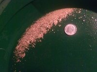
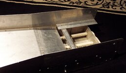
Planning New FB Gold Trap....

You don't want the deck tooooo smooth. A slightly rough surface aids in separation/stratification of the material.

hes right... maybe you could rivet a piece or 1/8" ABS to it. i got a 3/16" piece of ABS with a slight texture to one side and it was 24"x36" from the plastic shop for $20
 

You could rough it up with course sandpaper a little to slow the material a bit and increase the separation time leaving the last 1/2 of the deck smooth but dropping big rocks on it wont scar or dent the surface at all.
 

hes right... maybe you could rivet a piece or 1/8" ABS to it. i got a 3/16" piece of ABS with a slight texture to one side and it was 24"x36" from the plastic shop for $20


Good Idea Tweeta Bear. :icon_thumleft:

However, slightly rough if anything would only slightly aid in separation.
I've found that material separates just fine across a smooth surface due to the specific gravity of the material combined with the proper 4:1 ratio of solids to liquids. Just as it does on a super smooth miller table.

Any friction provided by a slightly textured surface below the flow will have very little impact on the separation of materials compared to the natural separation caused by the varying specific gravity of the material in the flow combined with the overall length of the slick plate.

GG~
 

Last edited:
damn GG your one smart guy, i learned some thing thanks:) (the 4:1 thing add a little more light in my head)
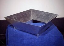
 

The 4:1 solids to liquids ratio is a general rule of thumb used by the mining industry to be in the ballpark, kind of like the 15 degree angle on sluices, it's not a hard and fast number. Although it does apply to to the full spectrum of ore washing equipment from hand sluices all the way up to full scale washplants.

GG~
 

Last edited:
Good Idea Tweeta Bear. :icon_thumleft: However, slightly rough if anything would only slightly aid in separation. I've found that material separates just fine across a smooth surface due to the specific gravity of the material combined with the proper 4:1 ratio of solids to liquids. Just as it does on a super smooth miller table. Any friction provided by a slightly textured surface below the flow will have very little impact on the separation of materials compared to the natural separation caused by the varying specific gravity of the material in the flow combined with the overall length of the slick plate. GG~

Happy to stand corrected on this one, thanks for setting us right GG!
 

Happy to stand corrected on this one, thanks for setting us right GG!

Kevin you were right in the first place, slightly rough does aid in separation. I was just saying that it's also ok to go smooth.

GG~
 

Last edited:
I have a plastic store in-town, planning on goin there to price out some ABS I will check out the uhmw....

Since we're talking skid plates....
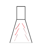
After seeing the water "V" through my sluice, I have wondered about putting some raised line's in a "V"...would this do anything ? From the underside I can press a line, causing a little raised ridge on the skid, i thought only a 1/8 or 1/10 or an inch or so ? Would this help the "V" ? Do anything beneficial like help seperation ? or, just slow me down.....


ie3.png
 

Try it and see what happens! You could try this with beads of silicone on a trial basis. Candidly, I am skeptical about it helping but hey, who knows?!
 

Try it and see what happens! You could try this with beads of silicone on a trial basis. Candidly, I am skeptical about it helping but hey, who knows?!

Thanks Kevin, skeptical as well, but figured, I'd see what others thought. Thinkin it could be a bad idea to add ridge's that could slow down the rate over the skid, but I am curious about trying to mess with the flow pattern, etc...Seems like when I have that good V or even X flowing through it that the pay flows nice & evenly, etc...watching it seperate & flow evenly when runnin like that made me think of adding the ridge's to always get that type of flow.

Guess I just need more experience / practice setting er up in the field, or Stream, !!!
 

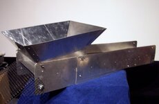
Finished the hopper.... weight 2-1/2 lbs.

hopper4.jpg

I think I could hit that from at least 6' away :tongue3:
Also thinking about adding a really thin lightweight flap to the out flow end of the hopper, something similar to the weight of a shower curtain.
hopper7.jpg


GG~
 

Last edited:
Been at it again.....
I really wanted to build something bigger, and that was my original plan....

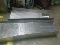
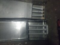
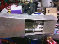
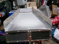
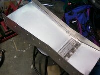
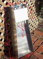
Somehow I ended up making roughly the same. There were severeal things I did not "like" on my first fluid trap build tho, so I am trying to get them resolved before getting too crazy.... You can see in the pic's the fluid tubes moved as I was silicon'in, I did not get my jets spaced exactly correct, and I did not connect them. The gold trap seems to fill easily and not stay fluid.

Hopeing the new one works a little better. Got some great Tips & Idea;s from GG..... Am taking more care with the fluid tubes, used a drill press to really get the jet holes spaced evenly. Still kept trap just wide enough to fit into a 5 gal bucket, but I did add 4-5 inch's to skid plate, and increased that piece to a .050 in thickness....I have almost punched through my original, (0.032). The screen will be cut down, probably in half, was just keeping it long to see the drop angle into the sluice.

All in all I am really happy with this one, and spent all of 15 $ on scraps for the build ! Had the PVC, and remnants from other builds. So that really helpd.

Hopeing to try it out this Saturday !!!

CAM00141.jpgCAM00142.jpg
 

One thing I am trying with my FB is a way to help keep the fluid bed fluid. I hope to get a test tube set up tonight.
My plan:
Take a regular PVC tube with holes drilled in the bottom and capped on the far end. Have one nipple on top to attach a tube going to a pressure gauge.
Put the tube in the flow of a stream and measure the pressure in the tube. Then attach a fitting on the upstream end that expands the diameter up to 3/4 and then 1 inch. See what effect this has on the pressure of the water in the tube.
Then I can press fit these adapters on in the field as conditions require in my BGT. By doing it this way I don't have to worry about changing the diameter of the holes in the tubes and can have good fluidization at lower flows/pressures. This will allow me to use my prospector 36" on marginal water flow without filling the trap and allowing material to overrun the fluid bed.
I have been looking up the charts for fluid bed dynamics and it seems that once you achieve a fluid bed, you have a larger room for error with too much pressure. The bed height will increase so I will have to worry about it rising too high, but I think it should be manageable. (edit: and the height of the fluid bed will slow material down that is running through so it should be easy to see if the bed height is slowing down material entering the fluid bed)
 

AL looks like 2014 is kicking 2013's..........
 

Been at it again..... I really wanted to build something bigger, and that was my original plan.... Somehow I ended up making roughly the same. There were severeal things I did not "like" on my first fluid trap build tho, so I am trying to get them resolved before getting too crazy.... You can see in the pic's the fluid tubes moved as I was silicon'in, I did not get my jets spaced exactly correct, and I did not connect them. The gold trap seems to fill easily and not stay fluid. Hopeing the new one works a little better. Got some great Tips & Idea;s from GG..... Am taking more care with the fluid tubes, used a drill press to really get the jet holes spaced evenly. Still kept trap just wide enough to fit into a 5 gal bucket, but I did add 4-5 inch's to skid plate, and increased that piece to a .050 in thickness....I have almost punched through my original, (0.032). The screen will be cut down, probably in half, was just keeping it long to see the drop angle into the sluice. All in all I am really happy with this one, and spent all of 15 $ on scraps for the build ! Had the PVC, and remnants from other builds. So that really helpd. Hopeing to try it out this Saturday !!! View attachment 955440View attachment 955441

Looks like your grizzly is going downhill :icon_scratch:
Are you going to add brackets to the sides so that it lays level and leaves a discharge port opening under it?

Like this.......
gt2.jpg


GG~
 

Good Eye GG ! You are correct, that grizzly is not mounted in the above pic, is just laying on the skid. I was anxious and started posting pic's before I finished :) That grizzley piece is also about 2x longer than it will end up. I was leaving it long & using my L square to see the level, and where I should mount the brackets to get the discharge port. For some reason, I like to mount the grizzly as my last step, then consider it finished ? No idea why, but should get it done tonight, we'll see if it works tomorrow. (Think I got it all sealed up last night)


**Quick side note, thanks for the PM about the fluid tubes, I actually have about 1 1/4 - 1 1/2 inches from the outer tubes to the walls of the gold trap, and a lilttle less than 2 inches between center tube and outer ones....think I was a little too OCD about "centering" the tube's. Still, figure I won't learn if I don't experiment. I'll see how this works, and already have a plan re-space those tube's.....
 

Top Member Reactions

Users who are viewing this thread

Back
Top