✅ SOLVED Test your skills on this one! Spent years trying to ID this.

musclecar

Full Member
Joined
Oct 15, 2006
Messages
132
Reaction score
1
Golden Thread
0
Location
Nampa Idaho
Detector(s) used
White MXT
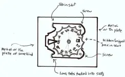
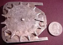
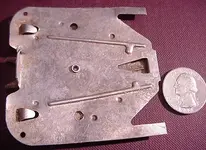
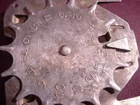
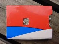
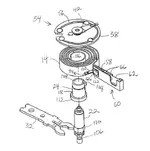
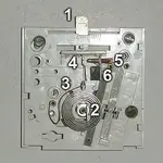
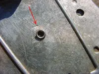
I found this in Alaska about 10 years ago, and have never been able to ID it. It is an aluminum piece, about 3 inches square. It has 15 teeth and is numbered 1-15. There is a stop preventing it from spinning freely. The back has two tabs that may have been used to mount it. ANY GUESSES?

Thanks,

MC

PS The quarter used for size was found yesterday! 1935S Yeah!
 

Attachments

  • dial1.webp
    dial1.webp
    67.3 KB · Views: 40,819
  • dial2.webp
    dial2.webp
    61.3 KB · Views: 38,926
  • dial3.webp
    dial3.webp
    60.1 KB · Views: 38,936
If the tab was in a slot of the potentiometer control arm it would not obscure the viewing window. My biggest issue with this item is it's orientation, as we tend to orient things vertically. The reason I thought it went to a baseboard heat register is that the controls are typically on the right end and access is tight vertically but the size seems correct from what I remember.
 

Upvote 0
Heres intimers diagram with the same idea reply #863. I dont know if it helps. :dontknow:
 

Attachments

  • counter2.webp
    counter2.webp
    11.7 KB · Views: 203
  • counter2.webp
    counter2.webp
    11.7 KB · Views: 204
Upvote 0
~ "Dueling Banjos Anyone?" ~

wwace ~

Seriously, you have my undivided attention, and I appreciate the input. I have read every word of your recent post's. However, I am still having some difficulty visualizing where the contacts and/or connections, etc., might hook up.

You can ask anyone on this website and they will tell you I am as bad as it gets with imagery - sizing - etc., etc. But something you might try, is to print out an image of the device, and then draw your ideas on top of it with red ink, and then scan - save - and send it back to us. Of course, this is just a suggestion, but it shouldn't be too difficult to do. (If I can do it - anybody can do it!) LOL :laughing7:

Thanks ...

Your researcher compadre for a common cause.

SODABOB
 

Upvote 0
wwace said:
If the tab was in a slot of the potentiometer control arm it would not obscure the viewing window. My biggest issue with this item is it's orientation, as we tend to orient things vertically. The reason I thought it went to a baseboard heat register is that the controls are typically on the right end and access is tight vertically but the size seems correct from what I remember.
WW, previously I put a cover over the numbered face and cut out a viewing window for the numbers. In this scenario, I didnt understand the need for the pointer. :icon_scratch:

If this were for a heater, it has no off position or zero. (like you said earlier)I think this would be dangerous. If someone tried to turn it counterclockwise to lower it they may hit #15 by accident.

Believe it or not, I am starting to like your idea of a heat thermostat/rheostat WW because its most logical. I just cant figure how it fits.
 

Attachments

  • MVC-036F.webp
    MVC-036F.webp
    73.4 KB · Views: 203
  • MVC-036F.webp
    MVC-036F.webp
    73.4 KB · Views: 198
Upvote 0
SODABOTTLEBOB said:
~ "Dueling Banjos Anyone?" ~

wwace ~

Seriously, you have my undivided attention, and I appreciate the input. I have read every word of your recent post's. However, I am still having some difficulty visualizing where the contacts and/or connections, etc., might hook up.

You can ask anyone on this website and they will tell you I am as bad as it gets with imagery - sizing - etc., etc. But something you might try, is to print out an image of the device, and then draw your ideas on top of it with red ink, and then scan - save - and send it back to us. Of course, this is just a suggestion, but it shouldn't be too difficult to do. (If I can do it - anybody can do it!) LOL :laughing7:

Thanks ...

Your researcher compadre for a common cause.

SODABOB
I didnt even know how to use a computer when I first joined TN. My brother had to do it for me. Its all a great learning experience.
 

Upvote 0
bigcypresshunter said:
Heres intimers diagram with the same idea reply #863. I dont know if it helps. :dontknow:

on the right track but there really isn't any need for a connecting rod as the tab fitting into a slot of the rheostat(whatever) as that is the simplest method. also the construction appears to weak to drive a timer motor or whatever.

A key feature to the device is the little indents on the back of the wheel mounting plate. They are there to prevent wobble in the wheel causing the control arm to disengage from the tab imo
 

Upvote 0
wwace said:
bigcypresshunter said:
Heres intimers diagram with the same idea reply #863. I dont know if it helps. :dontknow:

on the right track but there really isn't any need for a connecting rod as the tab fitting into a slot of the rheostat(whatever) as that is the simplest method. also the construction appears to weak to drive a timer motor or whatever.
A key feature to the device is the little indents on the back of the wheel mounting plate. They are there to prevent wobble in the wheel causing the control arm to disengage from the tab imo
Yes the diagram in the way intimer drew it will not work but the idea is the same I think.
 

Upvote 0
bigcypresshunter said:
wwace said:
If the tab was in a slot of the potentiometer control arm it would not obscure the viewing window. My biggest issue with this item is it's orientation, as we tend to orient things vertically. The reason I thought it went to a baseboard heat register is that the controls are typically on the right end and access is tight vertically but the size seems correct from what I remember.
WW, previously I put a cover over the numbered face and cut out a viewing window for the numbers. In this scenario, I didnt understand the need for the pointer. :icon_scratch:

If this were for a heater, it has no off position or zero. (like you said earlier)I think this would be dangerous. If someone tried to turn it counterclockwise to lower it they may hit #15 by accident.

Off would be controlled by a secondary switch, line voltage thermostat, circuit breaker or simply plugging it in and yeah I thought of the danger also but most heating devices have some other overheat protection. Also I have seen rheostats with detents which if equipped would make setting the dial have a "feel to it" but I admit this info seems a little fishy
 

Upvote 0
the adjustment with the finger tip could set something else like a thermostat? (not really sure)
but because there are no stops for each number it may flow to set another device that controls heat, cold or other...? :icon_scratch: :help:

i'm just guessing but old refrigs. is still a possibility in my opinion.
 

Upvote 0
The stop tab is very short but Ill try to look at an old heating thermostat I have at my warehouse tommorrow. It may be easier to visualize this thing.

I think the stop tab would ride here. bimetal_temperature_coil w tab arrow.webp

You would think it would leave some circular marks on the wheel face and the coil would obscure the numbers, I think. :icon_scratch: Maybe someone can try to photoshop this coil onto the wheel face.
Put the stoptab at the arrow point.

I gotta go LOL. This thang is taking over my life. :D
 

Upvote 0
bigcypresshunter said:
The stop tab is very short but Ill try to look at an old heating thermostat I have at my warehouse tommorrow. It may be easier to visualize this thing.

I think the stop tab would ride here.


You would think it would leave some circular marks on the wheel face and the coil would obscure the numbers, I think. :icon_scratch: Maybe someone can try to photoshop this coil onto the wheel face.
Put the stoptab at the arrow point.

I gotta go LOL. This thang is taking over my life. :D
there would have been an isolator gasket made from a stiff paper, to prevent the wheel from interfering with the coil operation
 

Upvote 0
intimer said:
the adjustment with the finger tip could set something else like a thermostat? (not really sure)
but because there are no stops for each number it may flow to set another device that controls heat, cold or other...? :icon_scratch: :help:

i'm just guessing but old refrigs. is still a possibility in my opinion.

I had thought of frig's also as the aluminum reminded me of the cheap freezer compartments inside the ones when I was a kid, but I dont recall or see a need for 15 settings, 5 would about cover the spectrum
 

Upvote 0
wwace said:
intimer said:
the adjustment with the finger tip could set something else like a thermostat? (not really sure)
but because there are no stops for each number it may flow to set another device that controls heat, cold or other...? :icon_scratch: :help:

i'm just guessing but old refrigs. is still a possibility in my opinion.

I had thought of frig's also as the aluminum reminded me of the cheap freezer compartments inside the ones when I was a kid, but I dont recall or see a need for 15 settings, 5 would about cover the spectrum
We thought of old Frigidaires also but there is no way of attaching the dial to the control. This bimetal coil idea, of yours and WW's, was not used on refrigerators as far as I know.


Keep in mind this has a pointer and I think that means an open face. As soon as somebody can photoshop my bimetal coil on the face of this thing, we will see if its feasable.
Unfortunately my printer just died. I could have cut out the coil and tried it.
 

Upvote 0
Hey ... I'm still here and wondering what they did along these "researching" lines before the invention of computers? ... Write letters? ... Can you imagine? Please don't respond to my dumb question, as I already know the answer ... (sort of).

Thanks!

:icon_scratch:

PRECOMPUTERBOB
 

Upvote 0
i don't see the coil you r image as directly connected to the bent up piece at #15. rather the finger tip would select a nuymber. that transferred that reqwuest via a direct connector to a device that activated a temperture sensitve....something.... heck just thinking the tab bent up was served as a connecting point telling it to adjust as requested by the i-14 setting.

yeah refrigs usually not that high number.... so just WAG i suppose... excuse me on the way through!!! ??? ??? ::)
 

Upvote 0
SWR said:
I think a bi-metal strip or element would be a better application than a coil
How would the tab on a round dial turn a straight bimetal strip? The bent up tab is the only connecting point and it moves in a circle.

A bimetal strip would need to connect on the bottom and we dont have anything on the bottom but a rivet and no shaft. http://www.aithermostat.com/bimetallic-thermostat.html
 

Attachments

  • thermo-3.webp
    thermo-3.webp
    5.8 KB · Views: 973
Upvote 0
intimer said:
i don't see the coil you r image as directly connected to the bent up piece at #15. rather the finger tip would select a nuymber. that transferred that reqwuest via a direct connector to a device that activated a temperture sensitve....something.... heck just thinking the tab bent up was served as a connecting point telling it to adjust as requested by the i-14 setting.

yeah refrigs usually not that high number.... so just WAG i suppose... excuse me on the way through!!! ??? ??? ::)
The bent up tab is the only connecting point and it moves in a circle and has to connect somewhere in wwace's theory. As far as I know, (in wwaces theory)the finger would select a number and the tab would connect to a bimetal coil spring at the red arrow point, tightening or loosening. As the temperature changes, the spring retracts or expands tilting the mercury bulb.
bimetal_temperature_coil w tab arrow.webpbimetal_temperature_coil w tab arrow.webp
 

Attachments

  • therm 5.webp
    therm 5.webp
    10.4 KB · Views: 942
  • Therm4.gif
    Therm4.gif
    34.1 KB · Views: 932
  • therm 5.webp
    therm 5.webp
    10.4 KB · Views: 954
Upvote 0
I think in fact the finger control on a thermostat turns an entire plate that has the bimetal coil fastened to it. But the numbers on our dial face would be concealed if the coil was on top. The bimetal coil (14) is usually under the dial as shown. 32 is a wrench to make fine adjustments (calibrations). In the HVAC trade we just install these things and calibrate them, we dont design them. :D http://www.hometips.com/how-it-works/thermostats.html
 

Attachments

  • thermostat patent.webp
    thermostat patent.webp
    27.2 KB · Views: 937
  • therm 5.webp
    therm 5.webp
    10.4 KB · Views: 968
  • Thermostat_bi metal coil.webp
    Thermostat_bi metal coil.webp
    16.5 KB · Views: 953
Upvote 0
SWR said:
bigcypresshunter said:
SWR said:
I think a bi-metal strip or element would be a better application than a coil
How would the tab on a round dial turn a straight bimetal strip? The bent up tab is the only connecting point and it moves in a circle.

A bimetal strip would need to connect on the bottom and we dont have anything on the bottom but a rivet and no shaft. http://www.aithermostat.com/bimetallic-thermostat.html

I think we've visited this before. Like I said, before...there was something more than likely something under the rivet that turned when the finger dial was turned. That closed/opened the distance of the bi-metal strip or capillary device. Similar to a rotary thermostat
Yes we have been over this before and I have inspected the bottom and unfortunately I can find no evidence that anything was ever under the rivet. At first I was exited to find a circular mark (red arrow), that upon closer examination, was most likely made by the rivet set. If there was a shaft coupling under the rivet, it may be a different ball game. Observe the scratches in one direction and nothing circular. IMO there is nothing on the bottom but a cheap rivet that has loosened up a bit..
 

Attachments

  • Alaska thang backside rivet.webp
    Alaska thang backside rivet.webp
    95.5 KB · Views: 926
  • thermo-3.webp
    thermo-3.webp
    5.8 KB · Views: 959
  • Alaska thang backside rivet.webp
    Alaska thang backside rivet.webp
    95.5 KB · Views: 919
  • thermo-3.webp
    thermo-3.webp
    5.8 KB · Views: 957
Upvote 0
Pardon my draftsmenship ... but

Here's how I visualize the device if mounted to a metal housing/plate of some kind.

I can't speak for where the so called contacts/connections might be ... but this might give us some idea of how it could mount to something. Please note that the long tabs are tucked into slots, as well as the "snipped" part, plus there are now screws in the mystery holes. :dontknow:

Just me being me ...

:hello:

BOB

P.S. In response to BigCy's mention of the two "curved" tabs on the underside, "maybe" they were flat to begin with, and ... as he said ... "optional." Aren't you proud of me? I reduced the image size all by myself! :notworthy: You're welcome ... LOL
 

Attachments

  • Draft Image.webp
    Draft Image.webp
    15.1 KB · Views: 896
Upvote 0

Top Member Reactions

Users who are viewing this thread

Latest Discussions

Back
Top Bottom