What's new

Resistivity machines...for real?

"G". Your assumption about resistive coils is not correct.

What I was trying to convey was about the resistive nature of soil at any one given point, time, and ambient. In other words, you cannot assume lower resistive coil measurement means or implies that there is any type of "thingy" between the measurement rods. Over a large statistical area, soil resistivity tends to be within a given range. This doesn't infer that over a small statistical area, the soil resistivity is constant. As I implied, even a foot or so displacement, can make a rather large change (up or down) in soil resistivity. Relaying on such a measurement as an indication of a treasure lying between the probes, is pure folly.
Absolutely!
All of the soils in the world are different. They have too many differences to list them here. But allow me to show the proof! I am both right and wrong! You are both right and wrong! Here's why!

Soil has different composition from one place to another. It has different resistivity from one place to another! The resistivity is different... But... the difference falls within a range of resistivities. The range of resistivities is different from one place to another! But... within the area of interest, resistivities are within a measurable "normal" for that area. Maybe 100 to 10,000 ohms (ohm-meters). It depends on the natural variables that contribute to the resistivites.

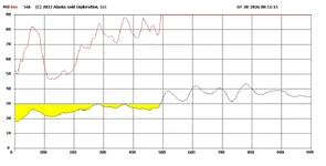
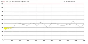
I have attached for reference a graph of a line of resistivity for a survey near Aniak, Alaska. It (the red line) shows continuous variation greater than ninety (90) and it's off scale. The scale only goes up to 90.

We are looking for conductors having resistivities less than 90.

Each horizontal pixel in each graph represents 12 feet (one sample). Each graph covers 1000 samples. There are three graphs * 1000 samples * 12 feet = 36,000 feet of survey...
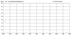
10010_ 0_56k.webp

The resistivities (red line) are greater than 90.

- Geowizard
 
Last edited:
Just for the record... The resistivity of soil is not consistent by any means. In fact, measurements just a few feet apart can vary by kiloohms, perhaps megohms. That fact alone, doesn't mean there is something buried between the probes. This inconsistency is one of the reasons amateur radio operators use radials to ensure a meaningful ground return current.

The argument is similar to folks who are convinced one specific detector and/or setting yields greater depth than another. While there is a possibility there might be a treasure between a pair of megger probes, soil conditions (acidic, alkaline, mineralization, etc.) are the main determining factors.
You are both right and wrong. I am right.

Here's why...

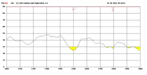
Every area of interest has a relatively normal degree of variation of resistivity from foot to foot over a variable amount of feet with variation forever over thousands of feet. Our area of interest has values that fall within a range of values. For example, Aniak, Alaska Survey;

10010_ 1_56k.webp

The resistivity is greater than 90 ohms along this section of survey with exception of two points that are lower than 90. The one in the middle is Gold. The other shows Gold but less gold.

- Geowizard
 
Last edited:
A third section of survey graphic;

10010_ 3_56k.webp

Shows the tail end of the survey.
 
Another 12000 foot section of another Aniak, Alaska survey line;

10060_ 0_56k.webp

Note the resistivity (red line) varies and the Gold varies!

Gold is measured on a scale of 30 to 0. Thirty (30) is the copper line. Gold is the ten (10) line. Silver is also ten (10). In-between is a mix of copper-silver-gold! Less than 10 sometimes happens for superconductors.

The supporting algorithm for gold info is found at www.uspto.gov.

After a few sessions, you start to get the idea! After thousands, it's just another day interpreting Gold in Alaska!

- Geowizard
 
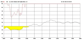
In all the excitement, I left out the graph for the third section where the real Gold is. ::)

10010_ 2_56k.webp

- Geowizard
 
Note: In the third section above, the gold is at the twenty (20) line. This is a variable mix of copper, silver, gold. From the graph, the deposit is about 300 samples * 12 feet = about 3600 feet long!

It's a land locked Spanish Galleon loaded with copper, silver and gold! Are we having fun yet?

- Geowizard
 
Last edited:
Discrimination of Gold?

Iron is conductive! I did research at www.uspto.gov. :icon_study:
I learned from "secret" patent information how to discriminate gold from Iron.

Iron is 90. Copper is 30. Gold and Silver are 10. In-between is a mixture. Iron suppresses Gold, making Gold look like iron or something in-between when mixed.

There are mystery metals that are conductive and are at 40 or 50, 60, 70, 80 etc.

There's more!

Geowizard.
 
Last edited:
Sample spacing;

These surveys show resistivity using an airborne metal detector (DIGHEM) flying along the survey line at 90 miles per hour. That equals 5280 * 90 / 3600 = 130 feet per second. The system measures the electromagnetic response ten times every second! That's about 130/10 = 13 feet.

The system measures at three frequencies, 56000 Hz, 7200 Hz, and 900 Hz. with two coil configurations, Coplanar and Coaxial. It measures to 400 plus feet at 900 Hz on a swath 60 feet wide. Do a search on DIGHEM.

- Geowizard
 
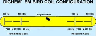
What are coplanar and coaxial coils?

dighem_bird_height.webp image courtesy Alaska DGGS
The horizontal coils are coplanar (in the same plane).
The vertical coils are coaxial (having the same axis).

This assembly is about 16 feet long. It is towed below the helicopter.

- Geowizard
 
Last edited:
Alternating DC;

The system needs time to settle between alternating current pulses. The switching sequence is "on positive", "off", "on negative", off... repeating. A simple DPDT switching circuit does the job and is low cost. For automation and precision, I use DPDT relays with a microcontroller.

View attachment 2263540<--Click me

This DPDT relay (R1) does the current reversal. A second DPDT relay (R2) in series does the On-off switching. The relay sequence is R1 ON, delay, R2 ON, delay, R2 OFF, delay, R1 OFF, delay, R2 ON, delay. R2 OFF. Repeating...

- Geowizard
You can buy, cheaply, an adjustable speed DPDT relay setup. No need for an Arduino, or any other setup. They cost about $10 on Amazon.
Jim
 
You can buy, cheaply, an adjustable speed DPDT relay setup. No need for an Arduino, or any other setup. They cost about $10 on Amazon.
Jim
Perhaps it is the speed of adjusting that could be too long / slow?
I like the cost factor and possible use if adjustment can be made faster?
 
The Arduino gives precision timing and does the data acquisition between and during pulses. Between pulses to capture voltage decay at a precise millisecond after turn off. At pulse time to measure resistivity. It can measure tx current and rx voltage instantaneously and record them on the SD card.

You can set up many electrodes and relays to precisely sequence through electrodes switching transmitter current and receiver voltages. measuring IP during decay time between pulses. Another measurement is Spontaneous or "Self" potential (SP. Sulfide orebodies operate like a lead-acid battery. They generate a voltage! SP) is measured after the voltage decay between pulses.

If you don't need that - then skip it! :thumbsup:

- Geowizard
 
Perhaps it is the speed of adjusting that could be too long / slow?
I like the cost factor and possible use if adjustment can be made faster?
Perhaps cheap and easy is not "better"!

-Geowizard
 
Perhaps cheap and easy is not "better"!

-Geowizard
Arduino is the next level of cheap and easy with a lot of people playing with it to look up what has been done.
 
Not my monkey.

- Geowizard
 
Perhaps cheap and easy is not "better"!

-Geowizard
As they say, " cheap is as cheap does"! We were once building a device and (at the time) the cost was getting to me , so I cheaped out and that device burnt up bcause I went with the cheap attitude ! Never again ! Always go with the better quality & the higher current value of a component ! The device we made was built to only be run for so long untill we got a line of trajectory and turn it off BEFORE the battery runs low and starts to raise the current as the voltage goes down and pops a 555 timmer and ruins your day ! Cheap lesson lerned BUT NOT forgotten !
 
Perhaps it is the speed of adjusting that could be too long / slow?
I like the cost factor and possible use if adjustment can be made faster?
Nah...once you have it set, you don't have to mess with it again. We currently have it reversing the polarity every two seconds. That's slow enough the metering at both ends can be read, but fast enough the readings aren't slowly changing, as they do when the probes are becoming polarized. it's working for us when we need it. Good to go! And it's capable of handling way more current then you'd ever get in a resistivity scan in dry soils.
Jim
 
Nah...once you have it set, you don't have to mess with it again. We currently have it reversing the polarity every two seconds. That's slow enough the metering at both ends can be read, but fast enough the readings aren't slowly changing, as they do when the probes are becoming polarized. it's working for us when we need it. Good to go! And it's capable of handling way more current then you'd ever get in a resistivity scan in dry soils.
Jim
Sounds good enough and I like the simple setup. Thanks.
 
Moving forward;

Advances in solid state devices have replaced vacuum tubes and relays. :occasion14:

I'm always on the prowl at electronics auctions for Power electronics. I come across some doozies! Power switching using IGBT devices and a relatively short list of related power switches improve the quality and reliability of switching. On the receiver side, analog signal switching can be done inexpensively as is done in modern metal detectors using low cost analog switches. For those unfamiliar with these devices, I recommend a brief refresh on the subject.

- Geowizard
 

Users who are viewing this thread

Back
Top Bottom